AXON Master
External access master for landings, entrances and doors. It holds the full card database on board, decides locally in a target under 2 ms without the cloud, and talks to per-floor nodes over two independent 250 kbit/s CAN buses.
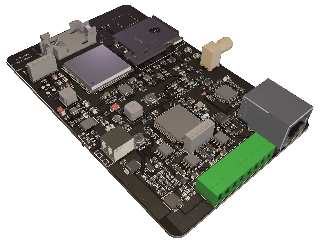
The decision-maker for the building side
AXON ICM-GE is the master for every access point outside the elevator cabin — landing readers, building entrances, internal doors and garage gates. In the AXON architecture it runs subsystem B: one master per building, one AXON Node per floor or door, and encrypted RS-485 readers behind each node. The master decides; the nodes report and execute. It holds the user roster, each card's per-node permission masks and validity dates, and the event log, and it sits between two networks: the cloud uplink above it and two CAN buses below it.
The reason the board exists is autonomy. The full card database lives in a 4 MB M95P32 page-EEPROM on the board, stored as sorted 64-byte records so a lookup is a binary search — a handful of SPI reads, with a design target of under 2 ms. Existence, blocked flag, permission mask and RTC validity are checked in that order and the verdict goes back to the node. The cloud, over Ethernet or LTE, only synchronises the database, collects logs and delivers OTA firmware. It is never asked for an access decision.
Below the master, per-floor nodes hang on two independent Classic CAN buses at 250 kbit/s — up to 120 access points per port, 240 per master, and masters are added side by side for larger sites, so the system itself puts no cap on floors or doors. Every node holds its own AES-128 key derived from the master's root key, every message is encrypted and MAC-tagged with anti-replay counters, and hardware acceptance filters mean a node never receives another node's traffic. Two ports let an installer split a tall riser — lower floors on one segment, upper floors on the other — and cut power to a faulty segment without touching the rest of the building.
What the board does for the site
Two independent CAN buses
Two FDCAN ports run in Classic CAN 2.0B mode at 250 kbit/s with an 87.5 % sample point, each with its own SN65HVD230 transceiver. Split a riser into lower and upper segments, or entrances and floors, without loading a single bus. Up to 63 addressed nodes per port, 120 Ω terminated at both physical ends.
Full card database on board
A 4 MB M95P32 page-EEPROM holds sorted 64-byte access records: 8-byte credential, four 64-bit permission masks (one per CAN port and relay, bit n = node n), valid-from and valid-to dates, flags and CRC-8 — up to 32,704 cards. A header sector carries magic, record count, CRC and sync sequence; the table is written into a second, inactive bank and the header flip is the last write, so a power cut mid-sync leaves the previous database intact. A card's permission is expressed per relay, not just per node: on a node driving two lifts, one record can grant lift 1 and refuse lift 2.
Per-node encrypted CAN link
Each node has its own AES-128 key derived from the master's CAN root key with AES-CMAC. Sessions start with a 3-pass mutual authentication, then every command and event is AES-CTR encrypted and CMAC-tagged with monotonic counters per direction. Compromising one node exposes that node only. A failed MAC or a replayed counter drops the session immediately and forces a fresh mutual authentication.
Connectivity comes with the board
A W5500 Ethernet controller reaches the AXON cloud over MQTT/TLS on port 8883. Alongside it an A7672E LTE Cat-1 modem uses a soft SIM — an eSIM profile written at the factory, with no plastic card to source, swap or lose — and the data plan is Axon Network, which carries the link in around 99% of the world. Cellular data transport is being finalised in firmware; Ethernet is the shipping uplink today.
Every decision recorded and reported
Every GRANT and DENY, with its reason — unknown card, expired or revoked, no permission for that node — is recorded the moment the decision is made and reaches the server with the master's telemetry. Management, reporting and OTA never sit on the access path. Durable on-flash log retention across a power cut is in development.
Switched, monitored bus power
A BTS7008-2EPA dual high-side switch feeds each CAN transceiver supply separately. Both ports come up about two seconds after boot in their last saved state, which the master keeps in its on-board flash; a factory-fresh board powers both. At runtime the master can cut power to a misbehaving segment — locally or from the server — while the other keeps running, and it reports each segment's current draw in milliamps.
One tap, end-to-end, without the cloud
Card read at the landing
A resident taps a MIFARE DESFire EV3 card. The AXON Reader authenticates it and sends CARD_EVENT with the UID to the floor node over secured RS-485.
Node forwards over CAN
The AXON Node re-wraps the event as N_CARD_EVENT under its own session key and sends it on the CAN bus. Only the master's hardware filter accepts it.
Master looks up and decides
Binary search in the M95P32 database, then in order: known? not blocked? node-and-relay bit set? RTC date inside the validity window? The verdict is GRANT or DENY with a reason.
Result, relays, log
M_ACCESS_RESULT carries decision, relay mask and pulse length. The node signals the reader and pulses its relays on grant; the master appends the event to its log.
Two uplinks above, two CAN buses below
Ethernet 10/100
A W5500 Ethernet controller on SPI is the master's preferred path to the AXON cloud. Traffic is MQTT over TLS on port 8883 with a per-board topic root; it carries database sync, event batches and OTA images. Give the master a dedicated switch port or a managed VLAN, with DHCP or a static address.
W5500 · MQTT/TLS 8883 · RJ-45LTE over Axon Network
The modem carries a soft SIM rather than a slot-mounted card: the profile is provisioned at the factory and the connectivity is Axon Network's, reaching roughly 99% of the world. The installer never sources a carrier SIM, negotiates a data plan or opens the enclosure to swap one. Cellular transport is being finalised in firmware; until it ships, Ethernet carries the uplink and the master keeps deciding offline either way.
A7672E · soft SIM · ~99% global coverage2× CAN, 250 kbit/s
Two independent FDCAN ports run Classic CAN 2.0B, 11-bit IDs, 250 kbit/s, 87.5 % sample point. The arbitration ID encodes direction, node ID and message type, so no two devices ever transmit the same ID and arbitration stays non-destructive. Nodes filter in hardware; 120 Ω at both physical ends of each segment.
Classic CAN 2.0B · 120 access points/port · 120 ΩThe numbers, from the datasheet
Values from the firmware and system specification of June 2026. Bus timing is per the CAN contract; the decision-time figure is the design target, not a bench measurement.
| Role | External master — landings, entrances, doors (subsystem B) |
|---|---|
| MCU | STM32H743VIT6, 400 MHz, 2 MB flash |
| Card database | M95P32 4 MB SPI page-EEPROM, 64-byte sorted records, up to 32,704 cards |
| Access decision | Local binary search, offline, < 2 ms design target |
| Node & relay permission | Four 64-bit masks per credential — per CAN port and relay, bit n = node n (0–62) |
| Time validity | RTC (32.768 kHz LSE), valid-from and valid-to dates per card |
| Event log | Decisions recorded locally and reported in telemetry; persistent flash log in development |
| Ports | 2× FDCAN, Classic CAN 2.0B mode, 11-bit IDs |
|---|---|
| Bit rate | 250 kbit/s, sample point 87.5 % |
| Transceivers | SN65HVD230, one per port |
| Addressing | ID = DIR(1) ‖ NODE(6) ‖ TYPE(4); node IDs 0–62 per port |
| Segment power | BTS7008-2EPA high-side switch, per port, remotely switchable, per-port current sense (mA) |
| Termination | 120 Ω at the two physical ends of each segment |
| Verdict latency | < 100 ms budget, measured path < 10 ms |
| Node offline detection | A node silent for 15 s is marked offline in telemetry |
| Ethernet | W5500 10/100, RJ-45 |
|---|---|
| Cellular | A7672E LTE Cat-1, soft SIM (eSIM profile) — data transport in development |
| Cloud protocol | MQTT over TLS, port 8883 |
| Uplink policy | Ethernet today; LTE over Axon Network in development |
| Cloud role | DB sync, event log, OTA — never the access decision |
| Firmware update | OTA over MQTT into a second flash bank, CRC-32 verified, atomic bank swap |
| Telemetry | 60 s heartbeat, switchable to a 1–600 s live mode with a TTL |
| Connectivity plan | Axon Network, ~99% global coverage — no carrier SIM to source |
| Node link | AES-128, 3-pass mutual auth, AES-CTR + CMAC |
|---|---|
| Key model | Per-node key derived from master root (AES-CMAC) |
| Anti-replay | 4-byte monotonic counters per direction |
| Session refresh | Re-auth on failure or node reboot; 10-min re-key |
| Secure element | ATECC608B on I2C (production key storage planned) |
| Card platform | MIFARE DESFire EV3 (AES, ISO 14443-4) |
| Input | 12 V or 24 V DC |
|---|---|
| Consumption | 4–8 W (15 W supply recommended) |
| Protection | Polarity-protected input, inline bus fuse |
| Mounting | DIN-rail, service-room cabinet |
|---|---|
| Service port | SWD debug header for commissioning; on-board service button |
| Indicators | Status LEDs: CAN 1, CAN 2, Ethernet, error, general status |
Terminals & connectors
First node segment on FDCAN1 through an SN65HVD230 transceiver. Transceiver supply is switched by the BTS7008 channel 0. Terminate 120 Ω at the two physical ends of the segment only.
Second, electrically independent node segment on FDCAN2, switched by BTS7008 channel 1. Use it to split lower and upper floors, or entrances and floors.
W5500 10/100 controller on SPI. Primary uplink to the AXON cloud over MQTT/TLS 8883; DHCP or static address.
A7672E LTE Cat-1 modem, fallback uplink. Route the antenna outside a metal cabinet; a poorly placed antenna inside a steel enclosure loses most of the usable signal.
12 V or 24 V DC, polarity-protected, inline fuse on the bus rail. Master draw is 4–8 W; budget separately for readers and node relays on the same rail.
SWD header for commissioning and on-site diagnostics, plus an on-board service button.
How ICM-GE compares
| Aspect | AXON ICM-GE | Cloud-only and Wiegand panels |
|---|---|---|
| Access decision | On the master, offline, binary search in a local 4 MB database | Round trip to a cloud API on every tap |
| Uplink | Ethernet today, LTE over an Axon Network soft SIM — no carrier contract | Single Ethernet drop — an ISP outage stops access |
| Wiring to access points | Two CAN segments on twisted pair, up to 120 access points each | IP cable and switch port to every door |
| Credential on the wire | AES-128 encrypt-then-MAC, per-node keys, anti-replay | Cleartext Wiegand D0/D1 over long runs |
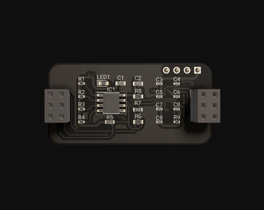
AXON Master, up close
Where AXON ICM-GE fits
Typical configurations we size for integrators. Every scenario below is a planning example, not a customer reference.
One node per landing, two segments
A 24-floor tower puts an AXON Node and reader at every landing. Floors 1–12 hang on CAN port 1, floors 13–24 on port 2, each segment terminated at its ends. Residents' cards carry per-node permission bits; the master grants their home floor and shared floors from its local database, whether or not the fibre is up.
Entrances and garage on one master
Three building entrances and an underground garage gate each get a node with an encrypted reader; a legacy Wiegand reader at the ramp joins through a Wiegand-to-RS-485 converter behind its node. One master in the basement service room decides for all of them, and the building manager opens the gate remotely with a standalone relay command.
Tenant doors with validity dates
A multi-tenant office runs the lobby, stair doors and each suite door as nodes on one master. Contractor cards are issued with a valid-from date and a permission mask limited to their client's floor; the master rejects anything else locally, and every decision, with its reason code, reaches the server for the property manager's reports.
Audit trail through WAN outages
Ward doors, medication rooms and plant rooms sit behind nodes on two CAN segments. Staff cards carry per-wing permissions in the permission mask, enforced on the master. When the hospital WAN drops, decisions continue locally and events are recorded on the master until the link returns.
AXON ICM-GE FAQ
Why CAN bus to the nodes and not RS-485 like the cabin?
How many nodes and how many cards does one master handle?
What happens when the internet is down?
Does a node decide on its own if the master is unreachable?
Can ICM-GE control access inside the elevator cabin?
What is the difference between ICM-GE and ICM-LR?
The rest of the AXON system
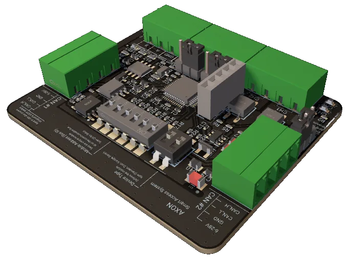
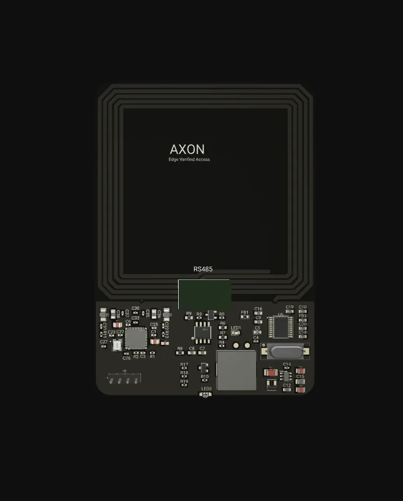
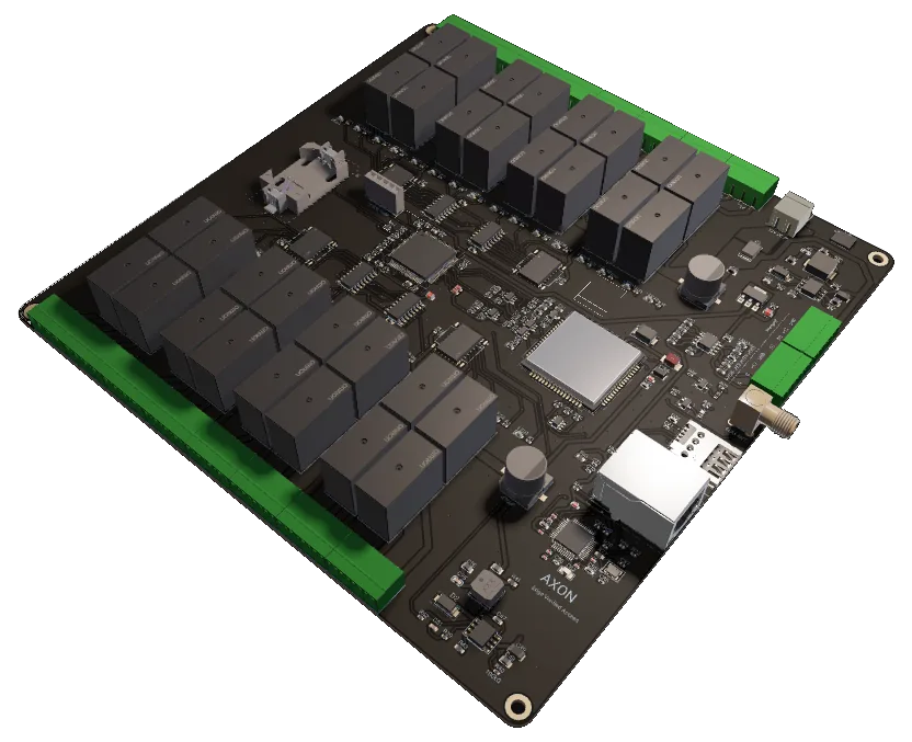
Ready to specify AXON Master?
Tell us the floor count, entrances and gates. We size the two CAN segments, node count and uplink for your building and supply AXON hardware from Kosovo.