AXON Smart Access
The master controller inside the elevator cabin. It reads encrypted card events from the in-cabin reader, decides locally which floors are allowed and pulses one relay per floor button — with no server in the critical path.
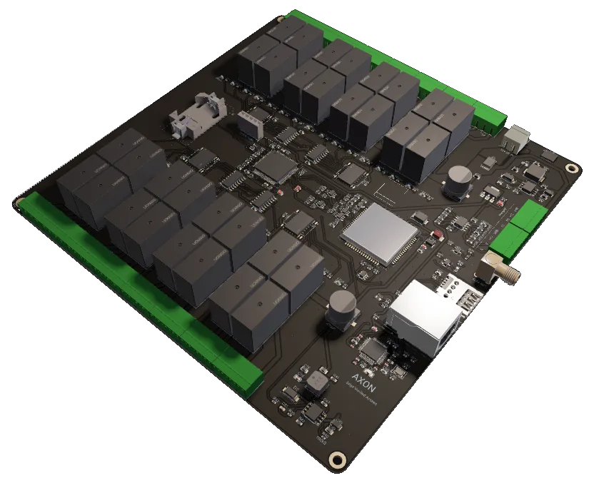
The decision is made inside the cabin
AXON CCU-32 is one of the two decision-making controllers in the AXON system. It covers subsystem A: the elevator cabin and the readers inside it. A card is presented to the cabin reader, the reader sends the event to the CCU-32 over an encrypted RS-485 link, and the CCU-32 decides on the board which floors that card may reach. The server is only used to synchronise the card database, collect logs and deliver firmware. No access decision waits for the network.
Floor control is done with 32 relay outputs, one per floor button. When a card is granted a floor, the matching relay pulses for 3 seconds and the passenger presses that button on the original panel. Nothing in the elevator's own call-button wiring is redesigned; the CCU-32 simply enables or leaves disabled the buttons a card is entitled to. The 32 outputs are driven through a chain of four 74HC595 shift registers from three MCU lines, and further units chain on the same cabin bus — so a taller panel is covered by adding units, with no upper limit on floors.
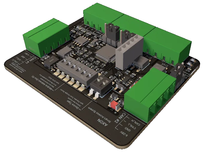
The controller is built around an STM32H563 (250 MHz, 2 MB flash, 640 KB RAM) with a W5500 Ethernet controller as the primary cloud transport and a SIM7000G LTE-M / NB-IoT modem as the fallback. Cloud traffic is MQTT over TLS to AWS IoT; firmware updates arrive over HTTPS into a two-slot OTA layout. The reader link is the same AES-128 secured RS-485 protocol used by the AXON Reader and the floor Node, so one reader firmware serves cabin and landings.
What the board does for the site
32 relay outputs from 3 lines
A chain of four 74HC595 shift registers turns three MCU signals (SRCLK, RCLK, SER) into 32 latched relay outputs. The firmware writes one 32-bit word; bit n drives relay n. Extending the register chain or adding further units grows the output count with no change to the control lines — floor capacity has no fixed ceiling.
Encrypted RS-485 reader link
The CCU-32 is the initiator of the AXON RS-485 secure layer: mutual authentication with the reader, a per-session key, AES-CTR encryption of the payload and an AES-128 CMAC over every frame with a monotonic counter. On the bench, 1000 encrypted taps carried zero UID bytes on the wire.
Access decision stays local
The reader authenticates the card; the CCU-32 verifies the frame and returns a grant or deny inside the reader's 1-second window. If a frame fails its counter or MAC check no verdict is sent, so the reader denies. The cloud is never queried for a decision.
Ethernet first, cellular fallback
A W5500 Ethernet controller on SPI is the primary transport for MQTT over TLS to AWS IoT and for OTA downloads. A SIM7000G LTE-M / NB-IoT modem on a second UART is the fallback path when the building has no cabling to the cabin or the wired link is down.
Two-slot OTA over HTTPS
Firmware images are downloaded with HTTPS range requests over Ethernet into a staging slot next to the active image. Metadata carries a magic tag, version and CRC32; the image is applied only after verification, so an interrupted download leaves the running firmware untouched.
Wiegand-26 input, legacy readers
Two interrupt-driven inputs (D0/D1) accept a standard Wiegand-26 reader directly: 8-bit site code, 16-bit card number and two parity bits. This keeps a retrofit running on the existing cabin reader while the encrypted AXON Reader is planned as the long-term option.
One card tap, end-to-end in the cabin
Card tap at the reader
The AXON Reader authenticates the DESFire EV3 card and sends a CARD_EVENT with the UID over RS-485, encrypted and MAC-protected with a fresh counter.
Frame verified first
The CCU-32 checks the counter and CMAC before parsing anything. A bad frame drops the session and triggers a re-handshake; no verdict is issued.
Local decision, verdict sent
The controller checks the card against its local permissions and replies ACCESS_RESULT to the reader within its 1-second window; the reader shows green or red.
Relays pulse, event logged
Granted floor relays pulse for 3 seconds so the passenger can press those buttons. The event is logged and published over MQTT when a link is available.
Two uplinks above, one encrypted bus below
Ethernet 10/100
A W5500 Ethernet controller on SPI1 carries MQTT over TLS to AWS IoT (status, card events, relay commands, OTA control) and the HTTPS firmware download. Give the controller a DHCP or static address on the building's management VLAN. It is the transport for OTA and bulk log sync.
W5500 · MQTT over TLS · DHCP or staticCellular LTE-M / NB-IoT
A SIM7000G modem on USART2 (115200 bps, up to 921600) provides an independent path when no cabling reaches the cabin or the wired link is down. Traffic is small — events, status and occasional OTA — so data use stays modest. Fit an external antenna: the steel cabin attenuates signal.
SIM7000G · LTE-M / NB-IoT · ext. antennaRS-485 reader bus
USART3 at 115200 bps, 8N1, half-duplex through a MAX3485 transceiver with DE/RE turnaround. The CCU-32 is address 0xFE and polls readers from 0x01 every 700 ms; frames start with 0xA5 and end in CRC16, with the secure layer inside the payload. The same protocol runs on the AXON Node.
115200 8N1 · SOF 0xA5 + CRC16 · AES-128The numbers, from the datasheet
Values from the cabin-master firmware and the CCU-32 engineering guide. Where the firmware and the guide differ, the firmware value is shown.
| Role | Cabin master (subsystem A: cabin + in-cabin readers) |
|---|---|
| MCU | STM32H563VIT6, 250 MHz |
| Memory | 2 MB flash, 640 KB RAM |
| Floor outputs | 32 relays per unit; units chain — no floor cap |
| Relay driver | 4× 74HC595 shift-register chain, 3 control lines |
| Grant pulse | 3 s per enabled relay |
| Card platform | MIFARE DESFire EV3 via AXON Reader |
| RS-485 reader bus | 115200 bps, 8N1, half-duplex, MAX3485 |
|---|---|
| Ethernet | W5500 10/100 on SPI (primary uplink) |
| Cellular | SIM7000G LTE-M / NB-IoT (fallback) |
| Cloud | MQTT over TLS to AWS IoT |
| Legacy reader input | Wiegand-26 on D0/D1 (interrupt inputs) |
| Local peripherals | SPI / UART |
| Input | 12–24 V DC |
|---|---|
| Consumption | 3–6 W |
| Protection | Reverse polarity, TVS on signals, surge on input |
| Recommended headroom | 10 W including the cabin reader |
| Reader link | Mutual auth, per-session key, AES-128 CMAC |
|---|---|
| Payload | AES-CTR encrypted, encrypt-then-MAC |
| Anti-replay | Monotonic counter, direction-bound MAC |
| Session re-key | Every 5 min |
| Reader liveness | Authenticated ping every 700 ms, 2.5 s timeout |
| Firmware update | Two-slot OTA, CRC32-verified, over HTTPS |
| Operating temperature | −20 °C to +70 °C |
|---|---|
| Mounting | Inside the cabin enclosure, dust-protected |
| Reader cable | Under 30 m recommended |
| Watchdog | MCU IWDG |
Signal map (from firmware)
TX on PB10, RX on PD9, DE/RE on PB14 (active high). 115200 bps 8N1 to the cabin reader(s).
PE2 / PE3 / PE6 into four 74HC595 registers. One 32-bit word latched per update, MSB first.
PD14 / PD15 on external interrupts for a legacy Wiegand-26 reader.
TX PD5, RX PD6, PWRKEY on PB8 for the SIM7000G power sequence.
SCK PA5, MISO PA6, MOSI PA7, CS PA4, RST PB1.
12–24 V DC from the cabin auxiliary rail, reverse-polarity and surge protected.
Where the CCU-32 differs
| Aspect | AXON CCU-32 | Cloud-only controllers |
|---|---|---|
| Where the decision is made | On the board, from local permissions | Network round-trip per tap |
| Behaviour when the uplink drops | Keeps deciding, queues events | Cabin stops authorising |
| Reader link | AES-128 encrypted RS-485 or Wiegand-26 | Often Wiegand cleartext only |
| Elevator integration | Relay per floor button, controller-agnostic | Frequently tied to one elevator brand |
| Firmware maintenance | Two-slot OTA, verified before apply | Site visit or no update path |
AXON Smart Access, up close
Where AXON CCU-32 fits
Typical configurations we size for integrators. Every scenario below is a planning example, not a customer reference.
Retrofit from keys to cards without touching the panel
A 25-floor residential tower with two cabins replaces key-switch floor access with cards. One CCU-32 per cabin holds the permissions; each resident's card enables their home floor plus garage and roof. No cabling reaches the cabin, so the cellular uplink handles sync and logs. Installation stays inside the cabin.
Tenant isolation enforced at the button
A multi-tenant office building gives each tenant its own floors. The CCU-32 pulses only the relays a card is entitled to, so a visitor cannot ride to another tenant's floor. The Ethernet uplink joins the building's management VLAN, and events are collected centrally over MQTT for audit.
Staff-only floors that guests never notice
A hotel keeps its top two floors for housekeeping and back-of-house. Guest cards are not permitted for those floors; staff cards are. Guests use the elevator as before, and the CCU-32 keeps deciding locally if the hotel's internet fails, with logs synced when the link returns.
Credential classes per ward floor
Each elevator carries a CCU-32 with permission sets for medical staff, administration, cleaning, contractors and visitors. Permission changes are pushed from the server and applied on the next sync; the cabin never waits on the network to grant or deny, which matters in a building that cannot afford a stalled elevator.
AXON CCU-32 FAQ
What does the AXON CCU-32 actually control?
Why 32 relays instead of wiring the buttons directly?
Does it work without internet?
Which readers can I connect?
How many floors can the system control?
How are firmware updates handled?
The rest of the AXON system
Ready to specify AXON CCU-32?
Tell us the number of floors, the cabin count and whether cabling reaches the cabin, and we will configure the CCU-32, reader and uplink for your building. The 32-floor unit is the standard configuration; taller buildings are covered by chaining units, with no upper limit on floors.