AXON Push-Button Bridge
A converter that taps the push-button lines and legacy signals of an existing elevator and frames them as AXON BUS events, so a modern access controller can gate calls without touching the cabin wiring or the controller's certification.
Add access control, keep the elevator
Replacing an elevator controller to add access control is the wrong tool for the job. The controller, its motor logic and its safety circuits are certified under EN 81-20 and tested under EN 81-50; opening that up multiplies cost and downtime when the actual goal is deciding who may call the cabin, where and when. AXON PBC-Bridge isolates exactly that signal layer. It is installed alongside the existing controller in the elevator cabinet, taps the discrete push-button lines and legacy controller signals that already exist, and hands them to the AXON Master as ordinary AXON BUS events. Nothing on the legacy side is replaced.
The bridge is a converter and only a converter. It samples its inputs, debounces the bouncing mechanical contacts that every old installation has, interprets each channel inside its own logical frame, and encodes the result as an AXON BUS message with a device address, event type and payload. Permission policy, time windows, lockdown and the audit log live one layer up on the Master, which has no special code path for bridges: an event from a retrofitted 1990s controller looks identical on the bus to an event from a native AXON Node. That split keeps the bridge small and the Master general-purpose.
Two modes cover the retrofit lifecycle. Converter mode is one-way: the bridge observes legacy signals and reports them, so an integrator can run an audit-only period and confirm the Master sees the expected events with no phantom presses from noise. Bridge mode is bidirectional: the Master's allow or deny comes back over the bus and the bridge asserts a legacy-compatible signal on the controller's input, so the elevator behaves as if an authorised user pressed its own button. Both modes accept 12 V or 24 V DC, because the regional installed base runs on a mix of both rails and one SKU should fit either cabinet.
What the board does for the site
Legacy signals in, AXON frames out
On the input side the bridge reads discrete contacts, voltage levels and timing patterns set by the original elevator manufacturer, each channel configured for its signal type. On the output side it emits standard AXON BUS frames with a device address, event type and payload, so the Master applies its usual handling.
Converter mode, then Bridge mode
Converter mode is one-way: observe legacy signals and report them to the Master, which suits an audit-only commissioning period. Bridge mode is bidirectional: the Master's allow or deny returns over the bus and the bridge asserts a legacy-compatible signal on the controller's input. Mode is selectable per unit.
Logical isolation per channel
Contactors, motor inrush and old insulation inject transients. Input filtering and debounce stop a noisy contact flooding the bus with phantom events, and logical isolation of the signal layer, in line with IEC 60747-5-5 optocoupler practice, contains a fault on one legacy input so the rest of the module and bus continue normally.
Fail-closed by default
Every step in the loop is bounded by a timeout. If the Master does not answer within the configured window, the bridge applies its per-channel failure policy. The recommended default for access events is deny, because opening access during an outage is the worse failure mode; fire-mode override channels are configured to fail open.
12 V or 24 V DC, one SKU
There is no consistent control-rail voltage across the elevator installed base in the region. The bridge accepts either rail, selected by terminal wiring in the cabinet, so no step-up or step-down converter is needed and there is no 12 V versus 24 V variant to stock or specify.
One address on a shared bus
The bridge is an ordinary addressable node on the RS-485 AXON BUS. Multiple bridges and other bus devices share one backbone with the Master through the riser: more devices means more addresses, not more home runs. A building with one legacy and one new elevator runs both on the same bus with one audit log.
From button press to elevator call
Sample and debounce
The bridge continuously samples push-button lines and legacy controller signals for state transitions, filtering contact bounce and transients so noise never becomes a bus event.
Frame and transmit
The event is interpreted in the bridge's own logical frame, encoded as an AXON BUS message with address, event type and payload, and published on the RS-485 bus.
Master decides
The AXON Master logs the event and applies permission policy and time windows, either centrally or from a short-lived local cache that stays subordinate to the Master.
Drive the legacy output
In Bridge mode the allow or deny returns over the bus and the bridge asserts a controller-compatible signal, matching the pulse or closure pattern the existing controller expects.
Two electrical worlds, one meeting point
Configurable input channels
A 1998 building with one manufacturer's controller looks nothing like a 2012 building with another's drive. The bridge treats each input as a configurable signal type, whether discrete contact, voltage level or timing pattern, sampled and interpreted per channel. The bridge adapts to the building; the building is not rewired for the bridge.
Contacts · levels · timing patternsRS-485 AXON BUS node
The bus follows the differential signalling of TIA-485-A, the baseline for multi-drop industrial busses. From the Master's view the bridge is an addressable node like any other: it has an address, publishes events and accepts commands. Keep the topology linear with short stubs, and never branch it into a star.
TIA-485-A · addressable nodeCentral or local
Central validation refers every event to the Master, giving one source of truth and one audit trail at the cost of a round trip. Local validation caches a recent decision for fast paths such as repeated calls from an already-authorised credential. A revocation on the Master invalidates the cache on the next central refresh.
Master authoritative · cache subordinateThe numbers, from the datasheet
Values below are confirmed design intent for the development unit. Channel count, current draw, final pinout and the supported controller list are being finalised through pilots.
| Role | Signal converter, retrofit bus bridge |
|---|---|
| Input | Push-button lines, legacy elevator controller signals |
| Output | AXON BUS frames, mapped protocol |
| Modes | Converter (one-way) · Bridge (bidirectional), selectable |
| Decision authority | AXON Master, central or local validation |
| Status | In development, function confirmed |
| AXON BUS physical layer | RS-485 differential pair (TIA-485-A), multi-drop |
|---|---|
| Addressing | One address per bridge, several bridges per bus |
| Topology | Linear bus with short stubs, no star branching |
| Legacy output | Asserted into existing controller in Bridge mode only |
| Supply input | 12 V DC or 24 V DC |
|---|---|
| Rail selection | By terminal wiring in the cabinet |
| Grounding | Single-point ground at cabinet, separate from motor circuit |
| Input conditioning | Debounce and transient filtering per channel |
|---|---|
| Isolation | Logical isolation of signal layer, IEC 60747-5-5 practice |
| Failure policy | Configurable per channel, default fail-closed for access |
| Credential storage | None beyond short-lived local-validation cache |
| Bus security | Inherits AXON BUS posture, authenticated framing planned |
| Form factor | DIN-rail-compatible, screw or pluggable terminals |
|---|---|
| Location | Existing elevator cabinet, alongside the controller |
| Bus cabling | Dedicated twisted pair, kept away from motor feeds |
| Commissioning | Start in Converter mode (audit-only), then Bridge |
Terminal groups (pre-release)
Samples the existing push-button signals from cabin and landings. Channel count and input range to be confirmed at release.
Interface for legacy elevator controller signals. The exact protocol set is under validation in field pilots.
Asserts signals back into the existing controller in Bridge mode. Disabled in Converter mode.
Differential RS-485 pair to the AXON backbone. Linear topology, short stubs, terminate correctly.
12 V or 24 V DC, rail selected by terminal wiring. Reverse polarity protection to be confirmed at release.
Module ground. Use a single-point ground at the cabinet to avoid loops with motor circuits.
Converter or Bridge. Selection method (DIP switch or configuration) to be confirmed at release.
How it compares to other retrofit routes
| Aspect | AXON PBC-Bridge | Common retrofit alternatives |
|---|---|---|
| Invasiveness | Sits alongside the existing controller; motor logic, safety circuits and certification untouched | Full controller replacement re-opens EN 81-20 certification and multiplies cost and downtime |
| Permissions and audit | Events framed on a real bus; the Master holds policy, time windows and the audit trail | Generic relay cards toggle inputs with no protocol mapping, audit log or central permissions |
| Device count | One bridge per elevator cabinet, where the signals already converge | Per-button local controllers multiply devices, cabling and maintenance |
| Cabling to the cabinet | One twisted pair through the existing riser | IP-per-elevator gateways need structured cabling most retrofits do not have |
AXON Push-Button Bridge, up close
Photographs are not published yet
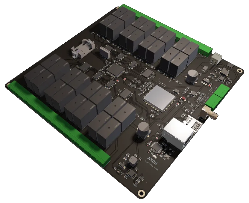
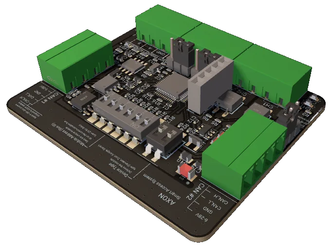
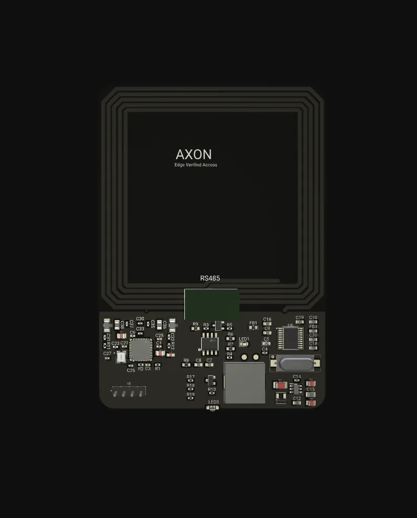
AXON PBC-Bridge is in development. Board photographs, final pinout and electrical ratings are released together with the production unit. Ask us for the current engineering status.
Where AXON PBC-Bridge fits
Typical configurations we size for integrators. Every scenario below is a planning example, not a customer reference.
Original controller, per-floor RFID
A 14-floor residential building keeps its manufacturer-original elevator controller and discrete landing call buttons. The bridge is installed in the elevator cabinet on the existing call lines; AXON Nodes with readers go on the landings; the Master holds the floor-to-credential mapping. Motor controller, safety circuit and travel logic stay under their existing certification.
Mixed-tenant time windows
A 9-floor office keeps a working early-2010s controller with legacy cabin push-buttons. Some floors are open in business hours, others restricted at all times. The bridge converts cabin presses into AXON BUS events, the Master applies per-tenant time windows, and the elevator answers only authorised requests. Tenant changes are a Master update, not a rewire.
Role-based wing access
Certain wings must be reachable only by specific staff classes while the elevator controller stays in place under its existing certification. The bridge converts call signals from the affected floors into bus events; the Master applies roles such as medical, administrative, cleaning, family and contractor; the audit log feeds compliance reporting. Visiting-hour changes are one configuration update.
Actively gated back-of-house calls
A hotel with two staff-only floors keeps its existing controller and routes landing calls for those floors through the AXON Master. Guest cards are simply absent from the authorised list. Bridge mode lets the Master actively gate the call rather than only audit it, which stops guests arriving on back-of-house floors by mistake.
AXON PBC-Bridge FAQ
What does the PBC-Bridge actually convert?
Does the bridge decide who gets access?
What is the difference between Converter and Bridge modes?
What happens if the AXON Master is unreachable?
Can one bridge handle multiple buttons or signals?
Is the PBC-Bridge available today?
The rest of the AXON system
Planning a retrofit with AXON PBC-Bridge?
Send us the elevator controller make, model and year, the number of call buttons and the cabinet rail voltage. We will confirm compatibility with the target controller and tell you where the module stands in pilots before you commit the project.