AXON Master E
The wired sibling of the AXON Master. Same decision engine and encrypted CAN backbone, no cellular modem — and readers and door relays connect straight to the board, so a small site needs one unit and no floor nodes at all.
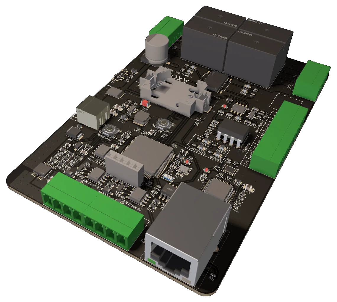
One board for a small site
AXON ICM-E is the AXON Master without the cellular modem, and with the first four access points built in. Where the ICM-GE reaches every door through a per-floor AXON Node, the ICM-E carries an RS-485 reader port, a Wiegand reader port and four relay channels on the board itself. A single entrance, a garage gate and two internal doors need one unit, one Ethernet drop and no bus wiring at all.
It is the same architecture underneath. The card database lives on the board, the access decision is made locally and never waits for the network, and the cloud is used only to synchronise the database, collect events and deliver firmware. Both CAN ports are still there, so the day the building grows past four doors you add AXON Nodes on a twisted pair instead of replacing the controller.
Dropping the modem removes the SIM, the antenna and the carrier subscription from the bill of materials. That is the right trade for a site that already has structured cabling and a switch port to spare — an office floor, a clinic, a small commercial building — and the wrong one for a site with no wired uplink, where the ICM-GE and its Axon Network connectivity are the answer.
What the board does for the site
Four relays on the controller
Four Omron relay channels, CH1 to CH4, are wired straight to the board's terminal blocks. A door strike, a garage gate, a barrier and an alarm channel can all be driven from the controller that made the decision, with no bus device in between and nothing to address.
Readers connect directly
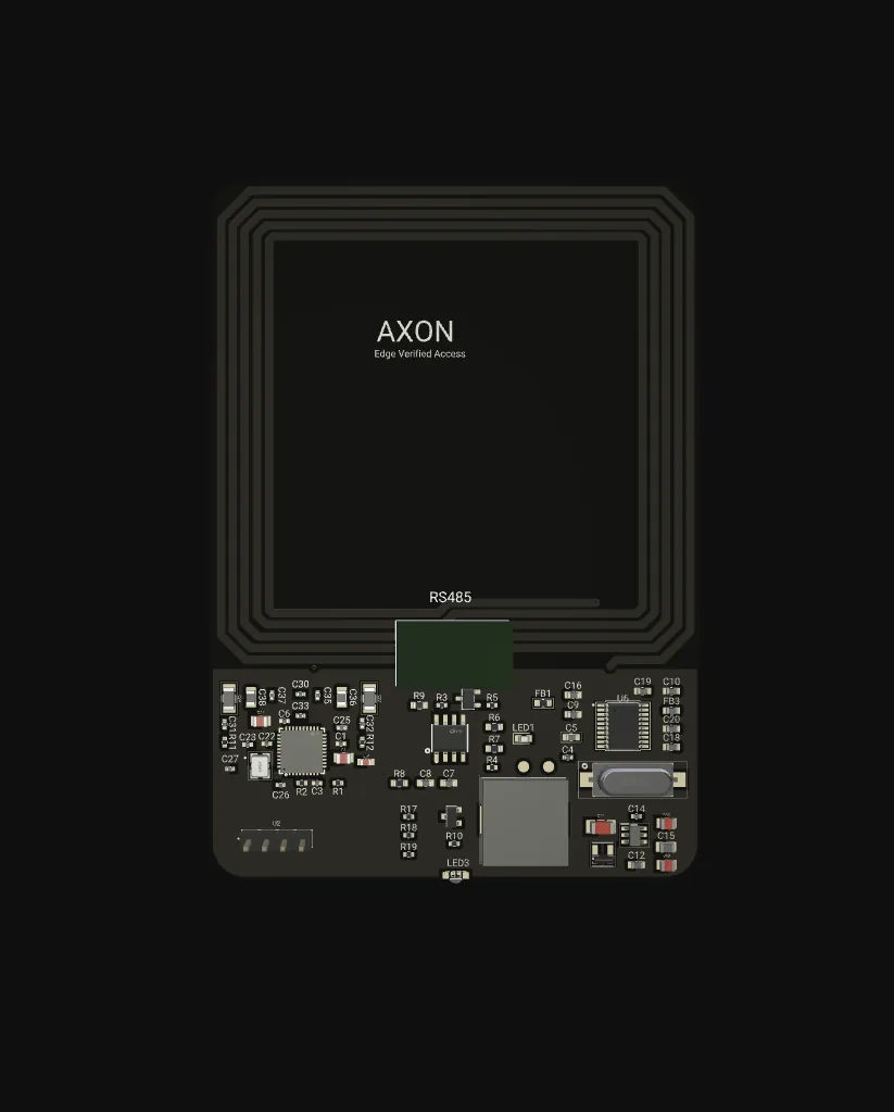
An RS-485 port carries the encrypted AXON reader protocol for a URX-Secure, and a Wiegand port takes any third-party 26-bit reader on D0/D1. Both terminals supply 12 V to the reader, so a door needs one four-core cable and no separate power run.
The decision stays on the board
The full card database sits in on-board flash — up to 32,704 records, looked up by binary search against the credential, its permission mask and its validity dates. No access decision waits for the network, so a switch reboot or an ISP outage changes nothing at the door.
Two CAN buses when the site grows
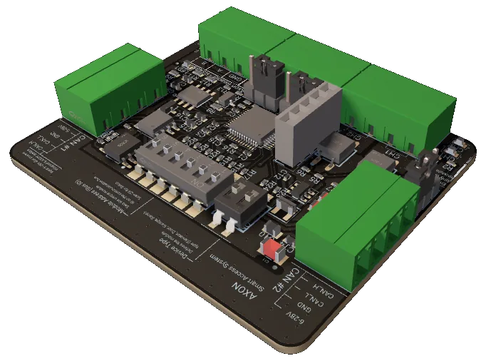
Both Classic CAN 2.0B ports at 250 kbit/s are fitted, each addressing up to 63 AXON Nodes. Start with the four on-board relays and add nodes on a twisted pair as floors or entrances are added, without changing the controller or re-issuing a single card.
Per-node encrypted CAN link
Every node on the bus has its own AES-128 key derived from the master's root key with AES-CMAC. Sessions open with a 3-pass mutual authentication, then each command and event is AES-CTR encrypted and CMAC-tagged with monotonic counters, so a frame cannot be replayed or moved to another node.
One wired uplink, used sparingly
A W5500 Ethernet controller reaches the AXON cloud over MQTT/TLS on port 8883 with DHCP addressing. It carries database sync, events and OTA firmware — never the access decision. There is no modem, no SIM slot and no antenna on this variant.
A door on the board itself
Card presented
A resident taps a DESFire EV3 card on a URX-Secure on the RS-485 port, or a legacy card on the Wiegand port.
Credential arrives
The reader hands the authenticated credential to the controller over the reader port — no bus hop, no node in between.
Local lookup
The master finds the record in its on-board database and checks the permission mask and the validity dates.
Relay pulses
On a grant it pulses the matching channel of CH1 to CH4 and records the event for the server.
Readers and doors first, bus second
Readers and 4 relays
One RS-485 port for an encrypted AXON reader and one Wiegand port for a third-party reader, both with 12 V supply on the terminal block. Four relay channels drive strikes, gates, barriers or signal lines directly from the controller.
RS-485 A/B · Wiegand D0/D1 · CH1–CH42× CAN, 250 kbit/s
Two independent Classic CAN 2.0B ports, 11-bit IDs, up to 63 AXON Nodes each. Split a building into two segments, or leave the ports unused on a small site. Segment power is switched on the board, so a shorted run can be isolated without a site visit.
Classic CAN 2.0B · 120 access points/port · 120 ΩEthernet only
A W5500 Ethernet controller on SPI, MQTT over TLS on port 8883, DHCP or a fixed lease. Give it a dedicated switch port or a managed VLAN on the building's management network. No cellular hardware is fitted on this variant.
W5500 · MQTT/TLS 8883 · RJ-45The numbers, from the datasheet
Values are read from the v1.4 board (AX-MAIN-02) and the shared AXON master platform; electrical ratings are confirmed at production release.
| Role | Wired access master — doors on board, nodes optional |
|---|---|
| Board | AX-MAIN-02, hardware v1.4 |
| Card database | On-board flash, sorted 64-byte records, up to 32,704 cards |
| Access decision | Local binary search, offline, no network in the path |
| Permission model | Per-node and per-relay masks, valid-from and valid-to dates |
| Real-time clock | On-board RTC with coin-cell backup |
| Relay outputs | 4 channels (CH1–CH4), Omron relays, dry contacts |
|---|---|
| Encrypted reader port | RS-485 (A / B / GND) with 12 V reader supply |
| Legacy reader port | Wiegand (D0 / D1 / GND) with 12 V reader supply |
| Card platform | MIFARE DESFire EV3 via URX-Secure; Wiegand 26-bit for retrofit |
| Ports | 2× Classic CAN 2.0B, 11-bit IDs |
|---|---|
| Bit rate | 250 kbit/s |
| Addressing | Up to 63 AXON Nodes per port |
| Segment power | Switched per port, on-board high-side switch |
| Termination | 120 Ω at the two physical ends of each segment |
| Ethernet | W5500 10/100, RJ-45 |
|---|---|
| Cellular | Not fitted — this is the wired variant |
| Cloud protocol | MQTT over TLS, port 8883 |
| Cloud role | Database sync, events, OTA — never the access decision |
| Firmware update | OTA over MQTT into a second flash bank, CRC-32 verified |
| Node link | AES-128, 3-pass mutual auth, AES-CTR + CMAC |
|---|---|
| Key model | Per-node key derived from the master root (AES-CMAC) |
| Anti-replay | 4-byte monotonic counters per direction |
| Reader link | Encrypted AXON protocol on RS-485; Wiegand is cleartext by nature |
| Input | 12 V or 24 V DC |
|---|---|
| Indicators | Status LEDs: CAN 1, CAN 2, Ethernet, error, general status |
| Controls | Bus-power button, reset button, service button |
| Service port | SWD debug header for commissioning |
Terminals & connectors
First CAN segment to AXON Nodes. Leave unused on a site that only needs the on-board doors.
Second, independent segment — a separate riser, wing or entrance group.
Encrypted AXON reader port with reader supply on the same block; one four-core cable per door.
Third-party 26-bit reader input with reader supply, for retrofits that keep existing readers.
Four dry-contact channels for strikes, gates, barriers or signal lines.
Uplink to the AXON cloud over MQTT/TLS. DHCP by default.
12 V or 24 V DC. Size the supply for the controller plus every reader and lock it feeds.
ICM-E or ICM-GE?
| Aspect | AXON ICM-E | AXON ICM-GE |
|---|---|---|
| Uplink | Ethernet only — needs a switch port on site | Ethernet plus LTE over an Axon Network soft SIM |
| First access points | Four relays and two reader ports on the board | Reached through an AXON Node on the CAN bus |
| Smallest useful system | One board, one Ethernet drop, four doors | One board plus one Node per door or landing |
| Growth path | Same two CAN ports — add Nodes when needed | Same two CAN ports, up to 120 access points each |
| Running cost | No SIM, no data plan | Connectivity included with the Axon Network SIM |
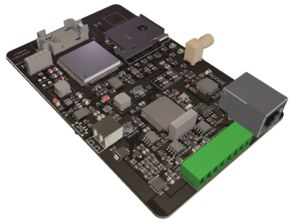
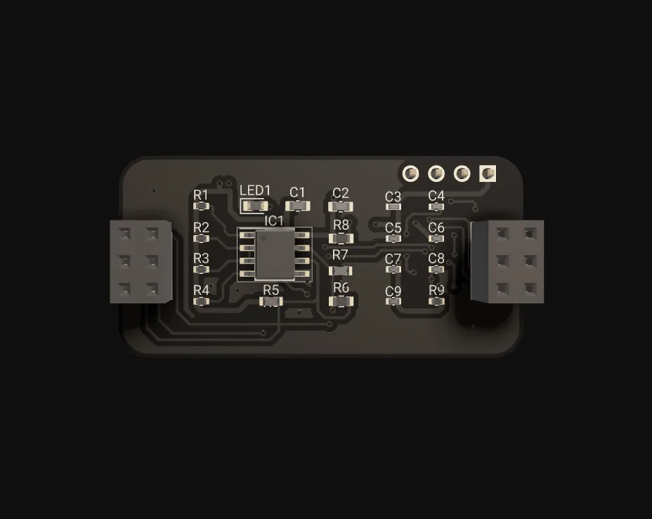
AXON Master E, up close
Where AXON ICM-E fits
Typical configurations we size for integrators. Every scenario below is a planning example, not a customer reference.
A whole building on one controller
Front entrance, staff door, records room and rear exit run from CH1 to CH4. One URX-Secure on the RS-485 port covers the entrance; the internal doors use the existing readers through the Wiegand port. No nodes, no CAN wiring, one Ethernet drop.
Keeping the readers already on the wall
A tenant fit-out inherits Wiegand readers at two doors. The ICM-E takes them on its Wiegand port and drives the existing strikes from its relays, so the visible hardware does not change while the decision moves on-site and the audit trail starts.
Four doors now, a riser later
A small building starts with the entrance and garage on the board. When the upper floors are fitted out, AXON Nodes go onto CAN port 1 on a twisted pair and the same controller, the same database and the same cards cover them.
Where a SIM makes no sense
A site with structured cabling and a managed switch has no use for a cellular modem, an antenna or a data plan. The ICM-E drops the lot and puts a dedicated VLAN port between the controller and the AXON cloud.
AXON ICM-E FAQ
What exactly is different from the AXON Master (ICM-GE)?
Can I still add floor nodes later?
Can I mix an encrypted AXON reader and an old Wiegand reader?
What happens if the network drops?
Which one should I buy?
Is it available now?
The rest of the AXON system
Four doors, or forty?
Tell us the entrances, doors and readers. We will say whether the ICM-E covers it on its own, or whether the ICM-GE and per-floor nodes are the better fit.