AXON Relay Add-on
A two-relay add-on for an existing AXON access installation. Each relay exposes NO and NC contacts, is commanded over the AXON BUS independently or together, and joins the bus without changing the main controller.
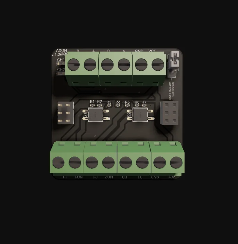
Add the output, keep everything else
AXON SC-E is the standard unit of relay expansion in the AXON access control topology. It adds two independently controllable contact outputs to an installation that already exists and already works, without a redesign of the main controller, the bus addressing model, or the access policy that lives on the AXON Master. Each relay has its own bus commanding, its own state and its own COM/NO/NC contact set. In the default independent mode the Master can drive Relay 1 active while Relay 2 stays inactive; a shared mode ties both relays to a single command when the two outputs form one logical action.
Most access systems are not built in one shot. A residential building adds a garage barrier two years after first occupancy. An office takes on a tenant whose floor needs a second locking arrangement. A hotel adds a staff-only utility door after a year of operation. In each case the required outcome is not "re-engineer the controller" but "add the output, keep everything else working". SC-E is shaped to be that minimal addition: it is wired in, given a unique bus address, and added to the access policy as a new output target. Existing time windows, lockdown behaviour and audit configuration are untouched.
Both contact forms on each relay are what make SC-E general-purpose. A maglock normally wires to NC so that loss of power releases the door — the fail-safe behaviour required for emergency egress. A door strike often wires to NO so that loss of power keeps the door locked. One SC-E can handle one of each, so the integrator decides fail-safe or fail-secure per output at install time, not at purchase. The relays follow the general-purpose electromechanical relay requirements of IEC 61810-1, with utilisation-category ratings declared per IEC 60947-5-1.
What the board does for the site
Two independent NO/NC relays
Each relay exposes COM, NO and NC terminals and has its own state on the bus. Wire a strike to NO, a maglock to NC, an indicator or alarm contact to either — one module covers a primary action plus a parallel signal at a single door cluster.
Independent or shared commanding
Independent mode is the default: each relay answers its own command and the two can sit in different states. Shared mode drives both from one command for outputs that form a single logical action. The mode is a deployment setting selected when the module is added to the installation.
One more node on the AXON BUS
From the Master's view SC-E is another addressable node on the existing RS-485 backbone. It receives commands, confirms state changes and follows the bus framing and addressing model. There is no special expansion-module protocol, so the Master's command path is the same one used for any relay target.
Add-on — main controller untouched
SC-E is strictly additive. The controller configuration is not reopened, so the tested access policy keeps applying and no re-validation is triggered — which in a hospital, school or multi-tenant office costs more than the electrical work. New outputs sit under the same policy framework as every existing one.
Fail-safe or fail-secure by wiring
The failure mode of each output is decided by the wiring, not the module: NC gives fail-safe (power loss releases the door), NO gives fail-secure (power loss keeps it locked). Both forms on every relay mean the choice is made per output at install time, and documented in the as-built.
Confirmed on bus, logged centrally
After a contact change the SC-E confirms the new state back on the AXON BUS. The Master records the action in the central audit — module, relay, trigger and time. Multiple SC-E units across a building report into the same Master and the same unified log.
One relay command, end-to-end
Trigger and policy check
A credential tap, schedule, emergency override or manual command reaches the AXON Master, which checks it against permissions, time windows and lockdown state, as for any relay action.
Addressed bus command
The Master issues an AXON BUS command addressed to the specific SC-E module and to Relay 1, Relay 2, or both when the module runs in shared mode.
Relay energises
The SC-E validates the frame and energises the addressed relay. NO closes, NC opens, and the wired strike, maglock, barrier or indicator responds.
Release, confirm, log
A timed pulse releases at the end of its window; a hold command stays until released. The SC-E confirms state on the bus and the Master writes the audit entry.
Same bus, same command path, no new cabling
AXON BUS over RS-485
SC-E connects to the existing backbone with its A/B differential pair, using balanced signalling per TIA-485-A — the standard physical layer for multi-drop industrial buses. Connect at the nearest point with a short stub, keep the topology linear and terminate only at the two physical ends of the bus.
TIA-485-A · A/B pair · unique addressCentral or local
Most commands are central: the Master evaluates an access event and dispatches the command. Local commanding covers relay actions that belong to a chained flow handled by other modules on the bus. The SC-E behaves identically either way — it acts on any valid bus command; who issues it is a system-design decision.
Master dispatch · chained bus logicNo new cabling, no new controller
SC-E adds no cabling of its own, no controller and no separate audit log. Every extra cable is a future maintenance liability and every extra controller a future divergence in policy. Riding the existing bus, SC-E inherits the installed infrastructure and stays under the same audit umbrella as every other node.
One bus · one Master · one audit logThe numbers, from the datasheet
Values below are from the AXON SC-E engineering documentation. Contact ratings, coil current and operating range are not yet published — ask before sizing heavy inductive loads.
| Role | Relay expansion add-on |
|---|---|
| Outputs | 2 relays, COM / NO / NC on each |
| Commanding | Independent (default) or shared |
| Integration | Add-on node — main controller unchanged |
| Availability | In stock for typical configurations |
| Bus | AXON BUS, RS-485 (TIA-485-A), A/B pair |
|---|---|
| Addressing | Unique bus address per module |
| Command source | AXON Master or local logic on the bus |
| Feedback | State confirmed on bus, logged on Master |
| Topology | Linear, short stub, terminate at bus ends only |
| Supply | 12 V DC |
|---|---|
| Sizing | Both relays active simultaneously + headroom |
| Ground | Single-point tie to system ground |
| Contact forms | NO and NC on each relay |
|---|---|
| Fail mode | NC = fail-safe, NO = fail-secure (by wiring) |
| Relay standard | IEC 61810-1; ratings per IEC 60947-5-1 |
| Inductive loads | Flyback diode (DC) or RC snubber (AC) at the load |
| Credentials on module | None — policy lives on the AXON Master |
|---|---|
| Bus security | Inherits AXON BUS framing and addressing |
| Fault isolation | Bounded to the module's two outputs |
| Roadmap | Per-device keys on the AXON BUS |
| Mounting | Standard cabinet or DIN-rail enclosure |
|---|---|
| Terminals | COM/NO/NC ×2, BUS A/B, +12 V DC, GND |
| Configuration | Mode select (independent / shared) + address |
| Roadmap | DIN-rail variants; higher contact-rating variants |
Terminals & connectors
First switched output, independent contact set. Wire the load to NO or NC according to the failure-mode behaviour the door or device requires.
Second switched output. Independent of Relay 1 in the default commanding mode; follows Relay 1 when shared mode is selected.
Differential pair to the existing AXON backbone. Short stub, linear topology, kept clear of mains and contactor-coil cabling.
Module supply for logic and relay coils. Size for both relays energised at once plus headroom.
Module ground. Tie to system ground at a single point to avoid ground loops.
Independent or shared commanding — how Relay 1 and Relay 2 respond to bus commands.
Unique bus address for this module. Two modules on the same address produce intermittent commanding.
Two relays, added without a redesign
| Aspect | AXON SC-E | Typical alternatives |
|---|---|---|
| Adding outputs | Add-on node on the existing bus; controller configuration stays closed | Swap to a larger controller — full policy re-validation and an outage during the swap |
| Audit and commissioning | One bus, one Master, one audit log | Generic relay board on a separate PLC — two logs, two commissioning paths, two failure modes |
| Right-sizing | Two relays and nothing else | Repurposed AXON Node — a reader endpoint under-used as a relay board |
| Command authority | Central on the AXON Master | Smart locks — one firmware path and one audit fragment per device |
AXON Relay Add-on, up close
Where AXON SC-E fits
Typical configurations we size for integrators. Every scenario below is a planning example, not a customer reference.
A second door added after commissioning
A building commissioned with AXON on one main entrance later gains a resident side door. An SC-E in the side-door cabinet drives the strike from Relay 1 on NO (fail-secure) and a status indicator from Relay 2. The Master gains one output target; residents use the same credentials at both doors.
Second locking arrangement for a new tenant
A mid-rise office takes on a tenant whose lease requires a second locking arrangement on their floor. Relay 1 drives the primary maglock on NC — fail-safe for code-compliant egress. Relay 2 sends a status signal to the tenant's own intrusion panel. Existing tenant policy on the Master gates both relays.
Utility door between wing and service corridor
A layout change adds a utility door between a controlled wing and a service corridor. Relay 1 drives the strike; Relay 2 drives a door-state indicator routed to central monitoring. Role-based policy — medical, administrative, cleaning, contractor — already exists on the Master and applies to the new output the moment it is added.
Staff-only door with a held-open alarm
A hotel adds a staff-only utility door after a year of operation. Relay 1 drives the lock; Relay 2 asserts an alarm contact if the door is held open longer than a configured window. The access policy gains one output and one alarm condition while front-of-house, cabin control and staff-floor access run unchanged.
AXON SC-E FAQ
What does AXON SC-E do?
Why two relays per module?
Independent or shared — which mode do I need?
Does adding SC-E require reconfiguring the main controller?
What power does SC-E need?
Can several SC-E units share one bus?
The rest of the AXON system
Ready to specify AXON SC-E?
Tell us how many outputs you are adding and what each relay drives. We size the supply, confirm NO/NC per output and ship from local stock in Kosovo — typical lead time for stocked configurations is one to two weeks.