AXON Solid-State Relay
A 32-channel solid-state output board for the AXON RS-485 bus. It exists for cabinets that switch many loads, often, for years — no contacts to wear, and one bus message for a whole channel group.
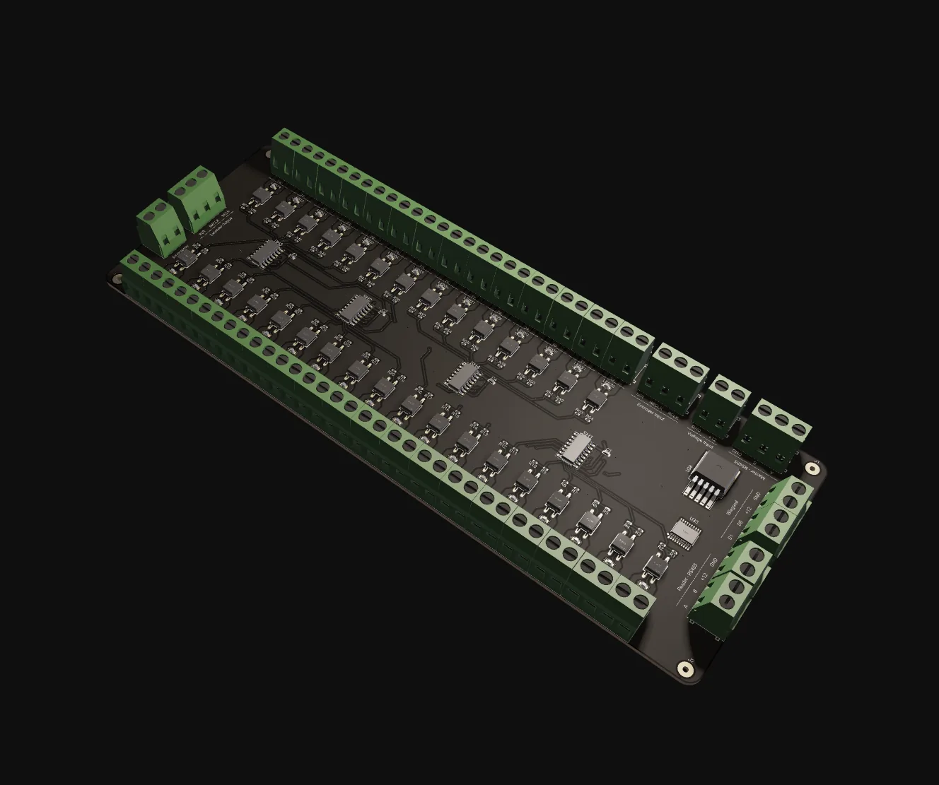
Many outputs, no contacts to wear out
AXON SSR-32 is the high-density output node of the AXON system. It sits on the AXON RS-485 bus, receives addressed commands from the master, and switches up to 32 independent solid-state channels — then reports the actual channel state back so the master supervises rather than assumes. Where RBN-2 covers two electromechanical channels right next to a load, SSR-32 covers the opposite case: many channels in one cabinet, switching often, for years. It does not read cards, authenticate users, or hold access policy. The master decides; SSR-32 executes.
Solid-state switching is a deliberate trade. There is no armature to fatigue, no contacts to pit, no spring to lose tension, so mechanical cycle life is effectively unlimited and the switching event takes microseconds. In return the elements have a non-zero on-state voltage drop, dissipate heat proportional to channel current, and need care with inrush, dV/dt and transients. For access outputs that cycle tens of thousands of times a year over a ten-year install, the contact-wear arithmetic gets uncomfortable. SSR-32 swaps a wear problem for a thermal-and-protection problem — one you engineer once, at design time.
The board is in development. What is fixed: 32 solid-state channels, RS-485 bus communication, per-channel and group command modes, and 12 V or 24 V DC supply. What is still in validation: per-channel current rating, AC-mains switching capability, thermal derating curves, isolation voltage and bus-level command authentication. Specify the architectural role in tenders — 32-channel solid-state expansion on the AXON bus — but do not pin electrical ratings until the production datasheet is published. Pilot integrations on planned installs are possible by direct arrangement with AXON.
What the board does for the site
32 solid-state channels per board
Thirty-two outputs on one board, each with its own A/B terminal pair and a per-channel status LED. No mechanical contacts, so no contact bounce, no chatter and no wear-driven maintenance. Failures, when they happen, are thermal or transient-driven — and typically confined to the single affected channel.
Addressed RS-485 bus node
Same physical layer as the rest of the AXON bus family: half-duplex RS-485 with direction control, one transceiver type, one termination discipline. Each board has its own bus address; the master targets a board, then a channel or group within it. Frames not addressed to the board are ignored.
Per-channel and group commands
Per-channel commands carry a channel index and duration — the common case of one credential, one floor or one door. Group commands carry a group identifier mapped at commissioning to a configured channel set, so cascade unlocks, lighting scenes and multi-floor authorisations are one message instead of thirty-two.
Supervised state reporting
After every command SSR-32 reports the actual channel state back to the master. The master supervises rather than assumes, which is what makes a relay board part of an access system: a stuck-on or stuck-off channel shows up in the master log instead of being discovered on site months later.
Hold-on-loss, CRC-checked frames
If the master link is lost, the default is to hold the last commanded state — the board never releases or triggers outputs on its own. Individual bus addressing and CRC-protected framing mean stray bytes or corrupted commands are dropped rather than partially executed.
12 V or 24 V DC supply
12 V matches the rest of the AXON family; 24 V is the standard control DC in industrial and elevator machine-room cabinets. The board accepts either without an external converter. Size the supply for realistic worst-case concurrent channel engagement, not for nominal quiet operation.
From master decision to switched load
Master decides
The AXON master applies credential, schedule, lockdown and group policy, and resolves which output channels must engage and for how long.
Command on RS-485
An addressed frame goes out on the bus: channel index plus duration, or a group identifier that maps to a configured channel set on the board.
Channels engaged
SSR-32 checks its address, parses the command, and its gate drivers turn on the targeted solid-state elements — microseconds for the switching event itself.
State reported, released
The board reports actual channel state back to the master. On a release command or expiry of the configured duration, the channel set turns off.
Why a 32-channel actuator lives on RS-485
AXON RS-485 bus
SSR-32 sits on the same RS-485 bus as RBN-2 relay nodes, reader nodes and the master tier. Linear backbone, short stubs, 120 Ω termination at the two physical ends only, shielded twisted pair daisy-chained through the cabinet. Each board carries its own address; the rest of the bus ignores traffic that is not for it.
TIA-485-A · half-duplex · 120 Ω endsOne twisted pair per cabinet
Parallel I/O ribbon does not scale past one cabinet — every output board would need a wide ribbon back to the master. Ethernet per output board adds switch ports, an IP plan and a per-board security surface for what is fundamentally a set-channel-state command. Addressed RS-485 framing carries that on a single pair with simple termination.
Addressed frames · CRC-protectedBoard, then channel or group
The master targets a board, then a channel or a group within it. Per-channel frames carry index and duration; group frames carry a group identifier resolved on the board to a configured set. The exact frame layout, CRC and group address space are part of the in-development specification and follow the other AXON RS-485 expansion nodes.
Per-channel · group · state reportThe numbers, from the datasheet
Design-intent values from the engineering deep-dive. Per-channel electrical ratings, AC capability, isolation voltage and thermal derating are still in validation and are deliberately not listed.
| Role | Output expansion node — does not decide |
|---|---|
| Channels | 32 solid-state, no mechanical contacts |
| Command modes | Per-channel (index + duration) and group |
| State reporting | Actual channel state back to the master |
| Link-loss behaviour | Hold last commanded state |
| Channel variants | 32 SSR (16 SSR listed in catalogue) |
| Status | In development — pilot by arrangement |
| Bus | AXON RS-485 bus (TIA-485-A) |
|---|---|
| Mode | Half-duplex with direction control |
| Addressing | Unique bus address per board |
| Framing | Addressed frames, CRC-protected |
| Termination | 120 Ω at the two physical bus ends only |
| Cable | Shielded twisted pair, daisy-chained |
| Channels | 32, each with an A / B terminal pair |
|---|---|
| Switching element | Solid-state, IEC 62314 class |
| Switching event | Microseconds |
| Isolation | Per-channel optical isolation (target) |
| Load class | Treat as DC-output until AC ratings publish |
| Indicators | Per-channel LED, commanded state |
| Input | 12 V DC or 24 V DC |
|---|---|
| Sizing | Worst-case concurrent channel engagement |
| Thermal | Heatsink area; allow airflow above board |
| Addressing | Stray bus bytes cannot engage outputs |
|---|---|
| Groups | Defined at commissioning, not open masks |
| Frame integrity | CRC — corrupted frames dropped |
| Message authentication | Bus-level auth in development |
| Over-current shutoff | Per-channel sensing under design |
| Mounting | Vertical, ventilated cabinet preferred |
|---|---|
| Terminals | Per-channel blocks, 32 output pairs |
| Load wiring | One load per pair; segregated load grounds |
| Inductive loads | External snubbers required |
| Labelling | Printed channel map inside cabinet door |
Terminals & connectors (target layout)
Differential bus pair; daisy-chain in and out through the cabinet.
Reference for the RS-485 transceiver.
Board supply; input voltage detected or selected per unit configuration.
One SSR output pair per channel. Wire each load across its own pair — one load per pair, no daisy-chained load grounds.
Per-channel indicator reflecting commanded state — the first thing to check when a channel does not switch.
Keep clear; allow airflow above the board inside the enclosure.
How SSR-32 compares
| Aspect | AXON SSR-32 | Alternative output hardware |
|---|---|---|
| Cycle life | No mechanical contacts; wear is not the failure mode | Mechanical relay boards: finite contact life, scheduled maintenance at high cycle counts |
| Integration layer | Plugs into the AXON master tier directly | PLC I/O modules: assume a PLC master and a PLC engineering toolchain |
| Channels per cabinet | 32 on one addressed bus node | Direct controller outputs: loom and board real estate dominate past about a dozen |
| Access-control behaviour | Hold-on-loss, supervised state, group commands built in | Generic Modbus SSR boards: rarely designed with these expectations |
| Two channels near the load | Use RBN-2 — simpler for that case | SSR-32 is for many channels in one cabinet at high duty cycle |
AXON Solid-State Relay, up close
Where AXON SSR-32 fits
Typical configurations we size for integrators. Every scenario below is a planning example, not a customer reference.
Floor authorisation from the machine room
A thirty-floor residential tower needs floor-level authorisation. SSR-32 sits in the elevator machine room, one channel per floor authorisation output to the elevator controller. The master holds the floor-to-credential map; on a valid badge it sends one group command authorising the resident's floor. Authorisation cycles thousands of times a month, so solid-state lifetime matters.
Corridor lighting and zone control
A city-centre hotel switches thirty-two back-of-house zones — corridors, service rooms, light circuits — from a combination of staff card events and time-of-day schedules. Group commands handle scene changes; per-channel commands handle individual staff events. An electromechanical board would need contact-life budgeting for this duty cycle; SSR-32 does not.
Per-bay availability and gate signalling
A parking facility has thirty-two bays with per-bay availability lights and gate signals. SSR-32 sits in the parking control cabinet and switches each bay output as cars arrive and leave, driven by occupancy events from the master. Per-channel commands cover single bay changes; group commands handle batch updates at shift change or facility-wide events.
Silent nurse-station indicator matrix
A hospital ward drives a matrix of nurse-station indicator lights and door-state signals across several wings. Each channel is one indicator; group commands handle wing-wide or shift-wide changes. Silent solid-state switching matters in a clinical environment where relay chatter is unwelcome, and no contact wear means no scheduled relay maintenance.
AXON SSR-32 FAQ
Is AXON SSR-32 shipping?
Why solid-state instead of mechanical relays?
What is the difference between per-channel and group commands?
Can SSR-32 switch AC mains loads?
Where does SSR-32 sit relative to RBN-2 and CCU-32?
Can I specify SSR-32 in a tender today?
The rest of the AXON system
Ready to plan around AXON SSR-32?
SSR-32 is in development. If a planned install needs high-density solid-state outputs, contact AXON for the current validation status, a pilot arrangement and the latest interface layout — and specify the architectural role in your documents, not electrical ratings, until the datasheet is published.