AXON Relay
A compact RS-485 bus node with two independent industrial relays. It puts the switching contact within a metre of the door, gate or light it controls, so one twisted pair replaces a building's worth of load wiring back to the panel.
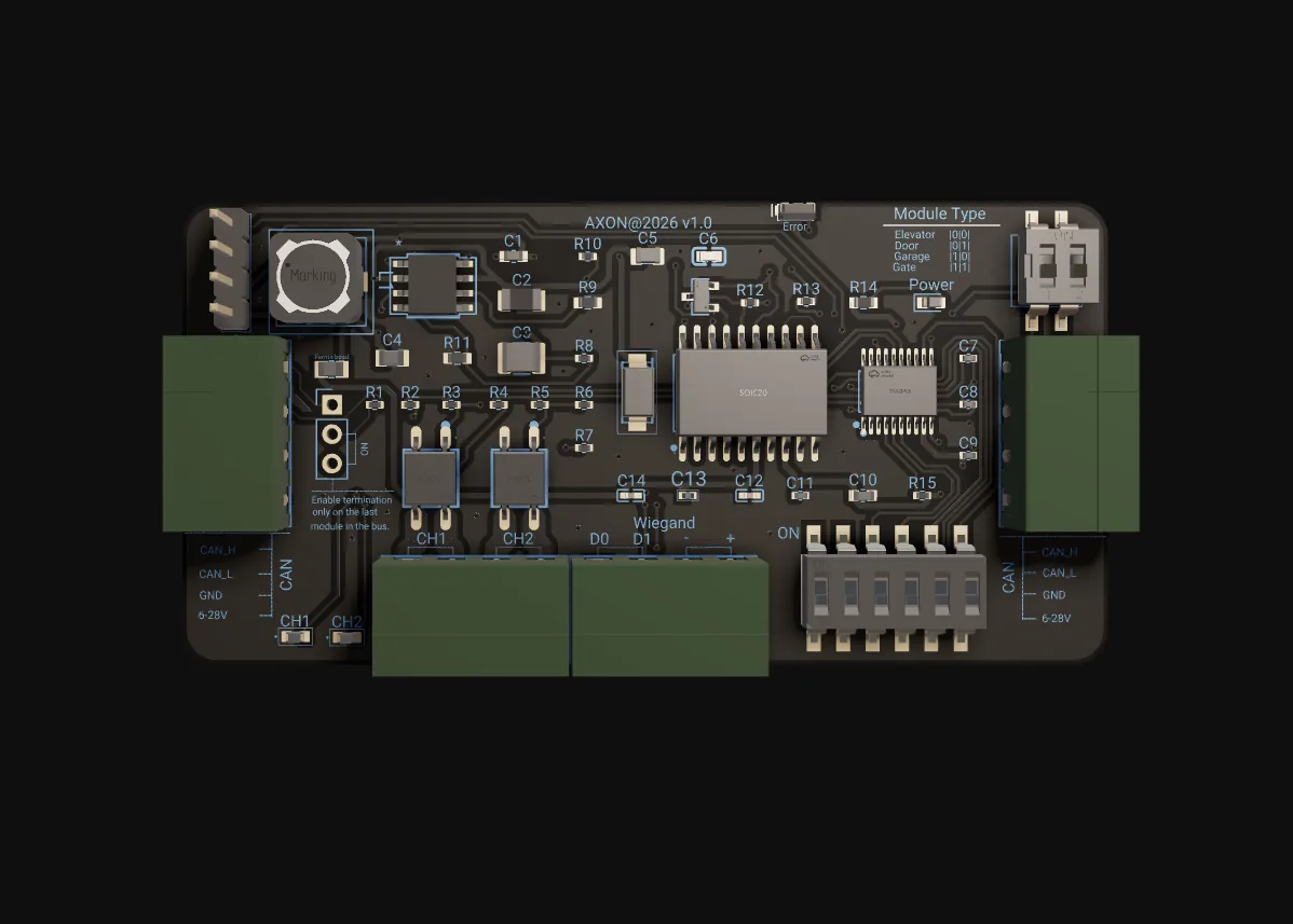
The relay belongs next to the load
AXON RBN-2 sits at the end of the decision path. Reader nodes capture credentials and the master decides; RBN-2 receives an addressed command on the RS-485 bus and closes a physical contact — a door strike, a maglock, a gate barrier pilot, a corridor light, an alarm sounder. It does not read cards, authenticate users or make access decisions. Keeping policy out of the output node is what makes a large install maintainable: when a rule changes, it changes once, at the master, and every relay in the building follows.
The "BN" stands for bus node, and the point of putting relays on a bus is geographic. Wiring twenty relays back to a central cabinet produces heavy switched-DC runs, voltage drop and a harness nobody can service. With RBN-2 you run one shielded twisted pair through the building, tap 12 V DC at each access point, and the relay sits within a metre of what it switches. Adding an output later means T-ing onto the pair and a local supply, not opening the panel.
The "2" is the second design decision. Many access points need two outputs at the same spot — door release plus corridor light, gate plus alarm, two zones in one room. Both live on one PCB with a shared bus stub, shared power tap and one enclosure, but the channels are logically isolated: a welded contact, blown driver or shorted load on channel 1 does not stop channel 2 from accepting commands. The module reports the failed channel to the master and keeps the healthy one running.
What the board does for the site
Two industrial NO/NC relays
Each channel is an electromechanical relay with COM, NO and NC contacts, rated 5 A at 30 V DC. Wire COM to the load common and pick NO or NC per application: energise-to-open for a strike, energise-to-lock for a fail-safe maglock. Chosen over solid-state because strikes, maglocks, lights and sirens behave differently electrically.
Logical channel isolation
A command targeting channel 1 never touches channel 2's state machine, and a fault on one driver does not block bus traffic for the other. The module reports the failed channel to the master and keeps switching the healthy one, so a blown light contactor never keeps a door shut.
Individually addressed on RS-485
Each RBN-2 has its own address on the AXON RS-485 bus and the master targets a specific channel within a specific module. Frames not meant for it are ignored, so a stray byte on the bus cannot engage all relays. Several modules share one segment as long as addresses are unique.
State reported, not assumed
After each command the module reports actual channel state back on the bus, so the master supervises the result instead of assuming it. A per-channel LED mirrors the commanded state at the board, which turns "is it the load or the relay?" into a thirty-second check with a multimeter.
Holds last state on link loss
If the RS-485 link to the master drops, the module holds the last commanded state by default. It does not release strikes or fire alarms on its own, because that would turn every transient noise burst into a false unlock. The master raises an offline-node alert instead.
Under 1 W idle, 12 V DC local
With no relay engaged the board draws under 1 W, so twenty modules idle under 20 W and share a small DIN-rail supply without a heat budget. Coil drivers include freewheel protection for inductive loads, and the relay contacts give galvanic separation between bus electronics and the switched load.
One command, one contact, one report
Master decides
The AXON master applies its permission rules to a credential or schedule event and decides that channel n on bus address a should engage for a defined duration.
Addressed command on the bus
The master sends an addressed frame on RS-485. Each RBN-2 reads the address and ignores frames not meant for it.
Relay pulls in, load powered
The targeted channel's driver pulls in the relay: NO closes and NC opens. The local DC load — strike, maglock, light, alarm — receives power across the contacts.
State reported, then release
RBN-2 reports actual channel state back to the master. On the release command or expiry of the engagement window the relay drops and the load de-energises.
RS-485: a long bus, short load wires
RS-485 multi-drop, half-duplex
A differential, multi-drop physical layer that runs across hundreds of metres of building cabling on ordinary shielded twisted pair, without repeaters. Every door, gate and light is already at the end of a wire run; RS-485 lets that same topology carry the command that closes the relay beside each one.
TIA-485-A · half-duplex · addressedDaisy chain, terminated twice
One backbone pair runs through the building; each RBN-2 hangs on a stub of 30 cm or less, or passes the cable through bus-in and bus-out terminals. Fit 120 Ω at the two physical ends only — across A/B with all modules powered down you should read about 60 Ω.
120 Ω × 2 · stubs ≤ 30 cm · no starDirect I/O or Ethernet per node
Wiring every relay back to the controller works for one door and collapses at twenty: forty load wires, voltage drop, a cabinet opened for every change. An IP stack per relay needs structured cabling, switch ports and a security boundary at each node. Ethernet belongs at the master tier, not the actuator tier.
Ethernet at master · RS-485 at loadThe numbers, from the datasheet
Published ratings from the AXON RBN-2 engineering documentation. The DC contact rating is published; AC switching is intentionally not advertised — drive an external contactor for mains loads.
| Role | Output expansion node — executes master commands |
|---|---|
| Channels | 2 independent, logically isolated |
| Decision logic | None on board — master decides, RBN-2 executes |
| State feedback | Actual channel state reported on the bus |
| Status indication | Per-channel LED reflecting commanded state |
| Relay type | Industrial electromechanical (IEC 61810-1) |
|---|---|
| Contact form | COM / NO / NC per channel |
| Contact rating | 5 A @ 30 V DC per channel |
| Contact options | NO, NC or NO/NC |
| AC switching | Not published — use an external contactor |
| Coil drive | Logic-level driver with reverse-EMF protection |
| Sustained engagement | Supported (energise-to-lock maglocks) |
| Bus | AXON RS-485 BUS, half-duplex with direction control |
|---|---|
| Addressing | Individual module address; per-channel targeting |
| Cable | Shielded twisted pair, daisy-chained |
| Termination | 120 Ω at both physical ends of the segment |
| Link-loss behaviour | Holds last commanded state |
| Supply | 12 V DC, tapped locally at the module |
|---|---|
| Idle consumption | < 1 W (no relay engaged) |
| PSU headroom | ≥ 10 W per local branch recommended |
| Load wiring | Under 5 m from terminal to strike or maglock |
| Mounting | DIN-rail-compatible form factor |
|---|---|
| Enclosure (indoor) | IP30 for lobby and corridor installs |
| Enclosure (outdoor) | IP65 with sealed cable entry for gates and barriers |
| Isolation | Galvanic separation bus side / load side via contacts |
Terminals & connectors
Differential bus pair; daisy-chain in and out where applicable.
Reference for the RS-485 transceiver. Do not loop it to the load ground.
Board supply. Tap it locally at the module's load location, not from a distant PSU.
Relay 1 contacts. COM to the load common; NO or NC selected by application.
Relay 2 contacts, independent from channel 1.
One per channel, reflecting the commanded state.
How RBN-2 compares to other output options
| Aspect | AXON RBN-2 | Generic relay boards & direct I/O |
|---|---|---|
| Channels per address | 2, each targeted individually by the master | Modbus boards address the module, not the channel; single-relay add-ons need a stub, tap and enclosure each |
| Fault behaviour | Failed channel reported; the other keeps running | On many multi-relay boards one channel fault takes the whole board offline |
| Wiring at scale | Long bus, load runs under 5 m | Direct controller I/O: forty load wires into one cabinet at twenty doors |
| Master required | Any AXON master with an RS-485 bus (CCU-32, ELM-GE, ICM-LR) | PLC-style I/O needs a PLC-class master to coordinate |
AXON Relay, up close
Where AXON RBN-2 fits
Typical configurations we size for integrators. Every scenario below is a planning example, not a customer reference.
Door strike and corridor light on one node
A mid-rise residential entrance runs one RBN-2: channel 1 drives the electric strike, channel 2 drives a contactor for the corridor light that a valid card should also switch on. The master commands both; if the lighting circuit trips upstream, the entrance still opens — and the reverse holds too.
Staff door plus front-desk alarm
A staff corridor between lobby and back-of-house: channel 1 holds an electric strike, channel 2 drives an alarm input on the front-desk panel. A staff card opens the door; an unauthorised attempt or forced-open event flags the desk. One address, one PCB, two functions that must not share fate.
Barrier pulse and warning light
At an office parking entry, channel 1 pulses the barrier motor relay and channel 2 turns on a flashing light while the arm moves. Mounted in an IP65 enclosure at the barrier, the RBN-2 executes both; a fault on the light circuit does not stop the gate cycling for the next car.
Maglock release with nurse-station indicator
A ward door uses channel 1 for an energise-to-lock magnetic lock and channel 2 for a nurse-station indicator. When the master de-energises the lock on a valid badge or emergency unlock, the indicator switches on so staff see the release. A maglock coil and a small LED feed behave very differently — isolation matters.
AXON RBN-2 FAQ
Why two relays on one board instead of one?
What does logical channel isolation mean in practice?
What loads can RBN-2 switch directly?
What happens if the RS-485 link to the master is lost?
Can a relay stay engaged indefinitely?
Where does RBN-2 fit in the AXON system?
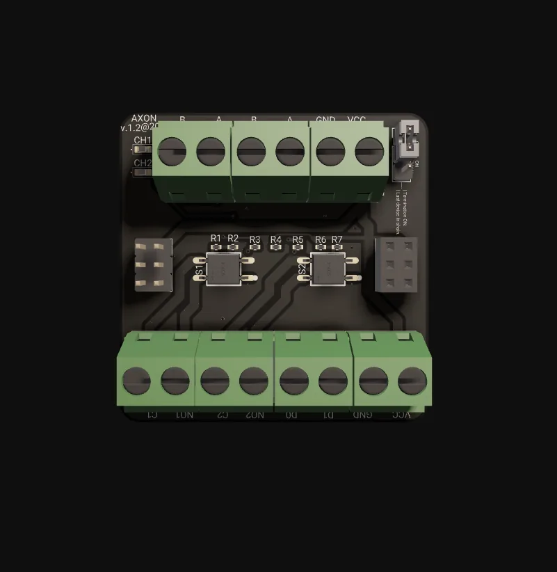
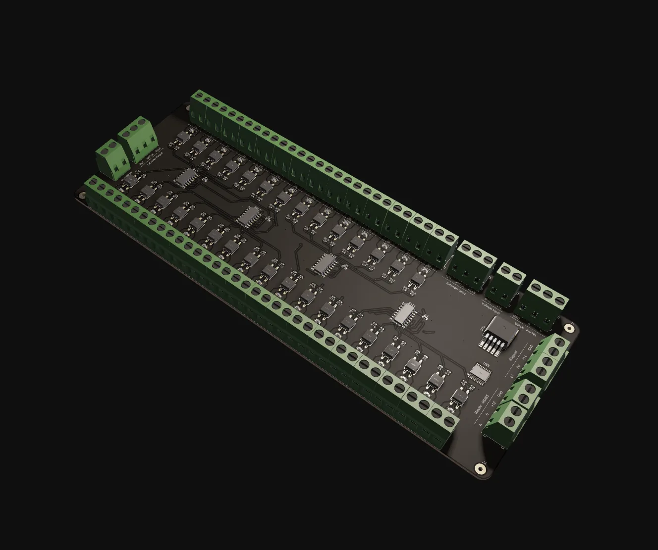
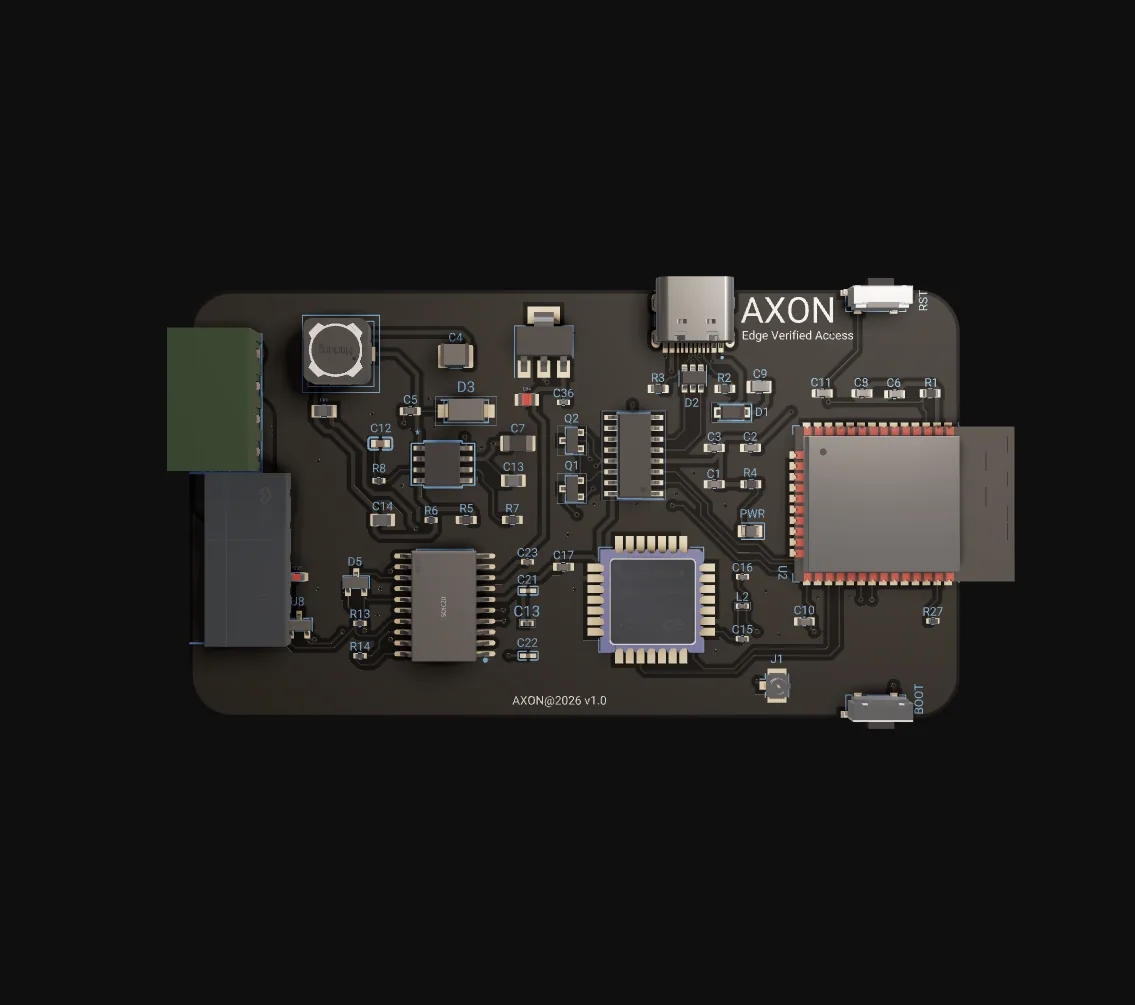
The rest of the AXON system
Ready to specify AXON RBN-2?
Tell us how many outputs you have, where they sit and what they switch. We supply RBN-2 from local stock in Kosovo and can plan the bus segment, addressing and PSU branches with you. Typical lead time for stocked configurations is one to two weeks.